Hello All, just a quick hello and maybe a gloat... ha ha. If your significant others or families need a push in the right direction this year, show them this. Happy Birthday to me indeed, Champagne, Tea at the Ritz in London (it was amazingly posh scran, yummy), Steak Dinner in the Savoy, an apartment for the weekend overlooking Houses of Parliament and Thames, and enough GW vouchers to buy an entire Tau Allies force... i'll get around to them soonish.
But I must confess, I am growing old now, but never growing up! Cheers everyone!
*EDIT And I got this cake! ;)
30 Nov 2014
26 Nov 2014
Chaos Warhound Project – interchangeable weapons
Hi again – we’ve got to the point in the project where I
need to look at weapons; a relatively small area of the build that has
significant impacts whether this model will ever be used on a gaming board.
If you are anything like me, whenever a model is larger than
a Dreadnought and has multiple weapons options, I always debate whether to make
the weapons interchangeable.
The pro’s are obviously cost and flexibility, but the con’s are
the fact that making weapons modular can often be a difficult and sometimes
detrimental (to the aesthetics) process. I find that sticking to a single
component allows the model to be built in a much more dynamic way, whereas
magnets can lead to a more static (or even unnatural) pose.
For the Warhound, I think the decision is a pretty easy
choice to make though. The standard loadout is the titan-sized Bolter and
Plasma guns – which are probably alright in a standard game of 40K and relatively
un-cheesey (although you mention titan and suddenly everyone thinks they are
unbreakable – but that’s a rant for a different post…), but with the advent of
Knights and D-weapons/super-heavies becoming more prolific because of the
Escalation changes, I need to be prepared to pull out the Turbo Lasers and join
in with some D-weapon shooty when the need arises.
So down the build…I decided against magnets for the weapons
– they are just too heavy and being attached at one end, I could see them
easily spinning, drooping and falling off. I might be wrong – but it wasn’t a
path I wanted to go down. Instead I used bolts. Specifically these ones
(well…actually not those bolts because they ended up being too long – the ones
I ended up using were a bit shorter).
Unfortunately I can’t tell you what size they are, or where
I got them from – I found them in my toolbox and there were enough for both
Warhounds. They could potentially be from a furniture pack as the nuts are for
allen keys….if anyone is particularly interested I could measure them. The important thing is that they had a
relatively shallow profile on the head and the nut had a similar convex to the
weapon-mounts concave.
First things first – I drilled out the titan ‘arm’. I
started with a small drill bit to make sure I went (mostly) straight through
the arm. I then used a series of drill bits to open up the channel to the
thickness of the bolt. I then used larger drill bits on the weapon-end of the
arm to countersink the nut. This was messy so I’d recommend the normal resin
precautions.
The top of the shoulders have a small hole – which is key to
how the interchangeable weapons will work; I will be accessing the screw
through there – so the bolt needs to be free to move in the arm.
I placed the
arm in the shoulder (with the bolt in) and made sure there was a mm or two gap
so that the bolt could spin freely. Then I attached the arm to the shoulder
using three pins – going through the shoulder into the arm at angles, being
careful not to damage the bolt when drilling the holes or using too much glue
on the pins (and gluing up the bolt).
The nut was then placed in the weapon and I tested that the
bolt still lined up correctly. I then glued the nut into the weapon in its final
position (the glue is only to hold it there temporarily – I wouldn’t expect it
to be strong enough for a permanent fix).
When the glue had set, one last check
that the bolt lined up and then I fixed the nut in place permanently by packing
greenstuff around it – being careful not to get any in the threads, or too
high. Once the greenstuff had cured I tested again and in this case I am happy
that the nut wont be going anywhere – although if I wasn’t, I would place some
small pins through the greenstuff and into the weapon to secure it.
Last thing; there are some covers for the top of the
shoulders – I popped a small magnet on the underside so that it stuck to the
bolt, but made it easy to access if I needed to (no pics of this yet…). And
there you have it – completely interchangeable weapons and all I need to do if
I get new ones, is fix a nut as above.
24 Nov 2014
Necron Cryptek #4
Hello All, thanks for dropping in. Here is a few pictures of my latest Cryptek. This is the actual Cryptek model from GW, made of finecast, which was an awful cast which needed some tlc and filling and some not so close up scrutiny. But, overall, not a bad job once done, I think it looks okay.
The original head has been used on my warrior converted Cryptek, and his 'coat tails' so other than that, it's not converted. I like the pose. Below shows the Cryptek with his squad.Thanks for reading! I'll have some more for you soon, I hope ;)
21 Nov 2014
Chaos Warhound Project – the torso
Hi again fellow titan fans! In the build process we now have
the base and legs built and I can make a start on painting them, but first I
need to tackle the torso.
I will definitely be painting the interiors, which I won’t
be attempting to do when it’s assembled, so this phase is all about dry-fitting
and pins (so sorry - its a bit dull...but hopefully it will be useful to some folks).
I’m not sure what to call the parts, but the torso is
basically split into 4 areas and the shoulder weapon mounts (I am treating the
head separately).
With those fixed, I then pinned the front compartment to the
rear with four more pins (it was tricky getting them all lined up, but the
areas will be completely covered, so there is no harm with a few errant test
holes…). Again, four pins is enough to hold the pieces together without glue.
Lastly was the shoulder weapon mounts – these seem really easy
to attach, but the weapons are pretty heavy and I will be using nuts and bolts so
that the arms are interchangeable – which means the shoulders need to be able
to take a lot of weight and punishment, so I ended up using 3 pins on each shoulder at
different angles; the resin will break before those joints do.
Pinning note – when I
am dry-fitting with pins, I only ever glue one end in – this means that the
angle and length won’t change and the joints will still fit perfectly later.
I now have an almost complete torso section that is
dry-fitted, so it’s just a case of pulling it all apart – although not the
shoulders (because of all the extra pins) and making a start on the interiors.
Note - not the final pose, it was just nice to balance the torso on the legs and finally start to see it come together...
19 Nov 2014
Chaos Warhound Project –getting mobile
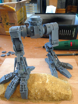
Hi all, so when I left off, I had built the first foot and received a second Warhound – since then I have built up a base, the second foot and legs up to the hips – which I think has taken in the region of 15 – 20 hours over the space of a few days (so yes – my girlfriend is loving the fact that all I’m doing at home is building this thing…)
Let’s start off with the base; the base a wooden cutting
board (roughly A4 size and 1cm thick) which will provide a solid foundation –
highly unlikely to tip over and thick enough to get some decent length pins in.
And only £4 from Tesco's (other cheap supermarkets are available). I bought two
– so that both Warhounds will be the same. It is completely possible to stand a
Warhound on its own feet without a base…but I just couldn’t see that happening…
This base will be scenic of course; the idea being that the
Warhound is stepping over a trench, so it will force the model to have a
dynamic pose and one which you don’t typically see these models having (most
have the posed mid-step at best). The trench wall is a chunk of polystyrene cut
to shape with some balsa wood panels and a few bits and pieces scattered
around.
Because the second foot will be standing on top of the
trench, I wanted to make sure there was a stable platform to take its weight,
so used two 2mm lengths of brass rod and drilled them through the polystyrene
and into the wooden board.
Corresponding
holes were drilled into the pad of the foot so that it sank just slightly into
the polystyrene.
Before I glued it into place, I sealed and coated the polystyrene
in sand (easier now than later). As with the other foot, because the weight of
the model is through the pad of the foot and not the toes, I didn’t need to
worry about pinning them too much. I actually built each toe section by section
(pinning in the same place as before) and curled them down around the trench.
Pistons were added as before and that was both feet done!
The legs – in my opinion the toughest part; whilst they are
fully articulate, there are a lot of big pieces to join that need to meet at
the hips – which is going to support some big chunks of resin. I decided to
dry-pin the legs so that they were articulate, but allowed me to play around
with poses. To do this, I drilled a hole through the centre of each joint and
inserted a paperclip. I played around with various poses until I had one where
the legs met nicely and the pose looked natural – at this point I fixed the
first foot to the base.
The foot was glued into place – which was strong enough
to fix it whilst I fixed two inch long pins through the foot and into the base
– it’s not going anywhere now.
A note on pinning – to get the strongest joint use two pins
at angles to each other, that way there can be no rotation and it’s impossible
(almost) to break the joint. This might mean fixing the first pin and then
drilling and placing the second after – so it can be tough to find places to
hide or cover the holes. Also – A hobby drill (like a Dremel) is a lifesaver on
project this size and well worth the investment.
After the feet, I focused on the lower legs, marking on the
ankle ball and foot socket so I could remove it and replace it in exactly the
same position later. I then glued and pinned the leg into place. Time for ankle
pistons (basically the same as foot pistons…)
At this stage the feet and lower legs are solid and the rest
of the legs are still connected by the temporary pins – so I was able to
temporarily add the waist section and connect to the hips with more temporary
pins. Now the entire lower of the titan is on the board and can manipulate the
articulate pieces simply by moving the waist around – I did this until I was
happy with the positions of all the leg components and marked them off. Then it
was simply a matter of a pair of pins through each joint and remove the
temporary pins.
Here only the feet and lower legs were glued - everything else was dry fitted with temporary pins - standing under its own weight.
With all the joints double-pinned I tested the structure to
see how stable it was – good, but there was a little play in one knee, which
over time may shift or distort, so I drilled and added another pin lengthways
through both pieces to support it.
Testing the lower half now, I would say that the legs could
easily hold 5Kgs of weight and I am able to pic the entire model up (including
board) from just the waist with no play, bending or wobbling. In other words –
bomb-proof!
Next time – starting the torso.
17 Nov 2014
Necron Doom Scythe with scenic base!
Here is the latest progress with the Necron ever-living, ever growing Army progress. A Doom Scythe, a heavy choice for a Codex: Necrons army list.
The Scythe itself is a new one, but the Doom Death Ray thing is from the first Night Scythe I did, I made that one a permanent Night Scythe and this one a fixed Doom Scythe. This is the third flying Croissant I have done. So two Night Scythes and one Doom for now....
The base was made using a foam resin barricade and cutting it to size, repainting and removing the fluff-like flock and matching it to my own base colours.
Still love the side profile of these flyers. Not a view you get to see often.
And a close up of the Death Ray!
Thanks again for stopping by.
16 Nov 2014
Chaos Warhound Project – double trouble!
A short non-building post today…
So a couple of days ago I had a Royal Mail pick up slip
pushed through my door – very strange as I hadn't ordered anything recently… in
fact the last thing I ordered was the Warhound. Me and LordH had a quick back
and forward joking about the possibility of being sent another Warhound by
accident.
…well…guess what it was? Another Chaos Warhound! A quick look at
my bank and order history and I have definitely only paid and ordered for one
and there is no trace of another being sent out on their systems, so it looks
like my titan is now the first of a pair of Warhounds! I’ll be honest – I can
live with these sort of customer service errors!
The plan for building the first Warhound is the same and I
will only be focusing on one at a time – it is probably too much to try and
build two simultaneously on my first titan project. It does mean however, that
I only need a Chaos Reaver now to take on Siph's Titan Maniple… LordH – you best get a
move on!
Subscribe to:
Posts (Atom)